Overview
This project combined mechanical energy conversion, analog electronics, and experimental validation into a single working system. The windmill drives a generator that produces an AC output, which then gets converted and conditioned into a usable DC signal. That signal is used to drive an indicator circuit that communicates turbine speed behavior during live operation.
The focus was not just building a circuit, but proving it with measurements. We tested the system across multiple wind speeds, verified rectified output behavior, and tuned thresholds so the indicator logic stayed stable under real, noisy generator conditions.
System Architecture
The system is built around a simple pipeline from physical behavior to user feedback:
- Wind input spins the rotor and drives the generator
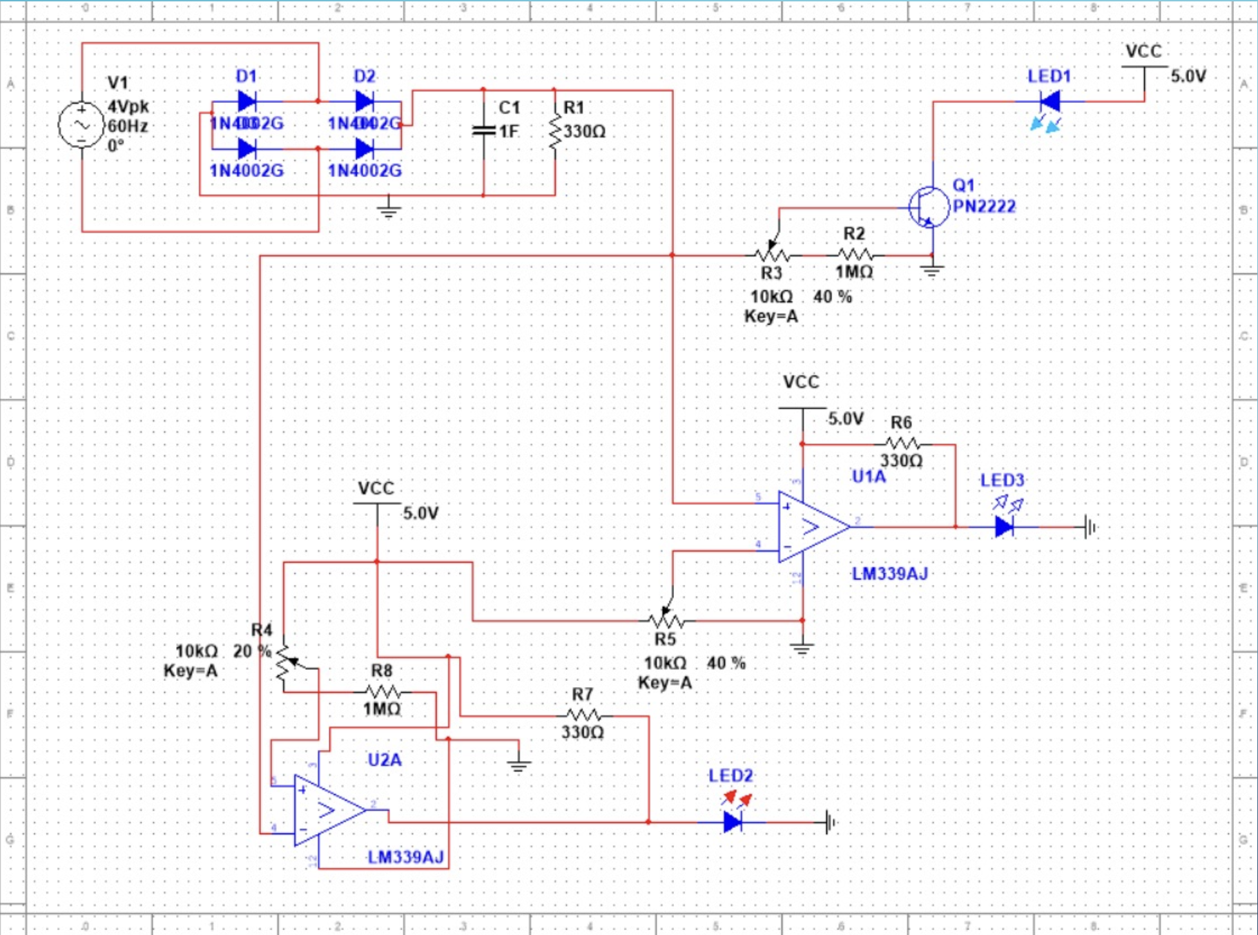
- Generator AC output feeds a full-wave rectifier stage
- Filtering reduces ripple and stabilizes the DC signal
- Comparator logic detects voltage thresholds tied to speed states
- LED outputs provide immediate speed feedback without needing instruments
Power Conditioning
The generator output varies significantly with turbine speed, so the first task was making that signal usable. The conditioning stage converts AC to DC and reduces ripple so downstream logic behaves consistently.
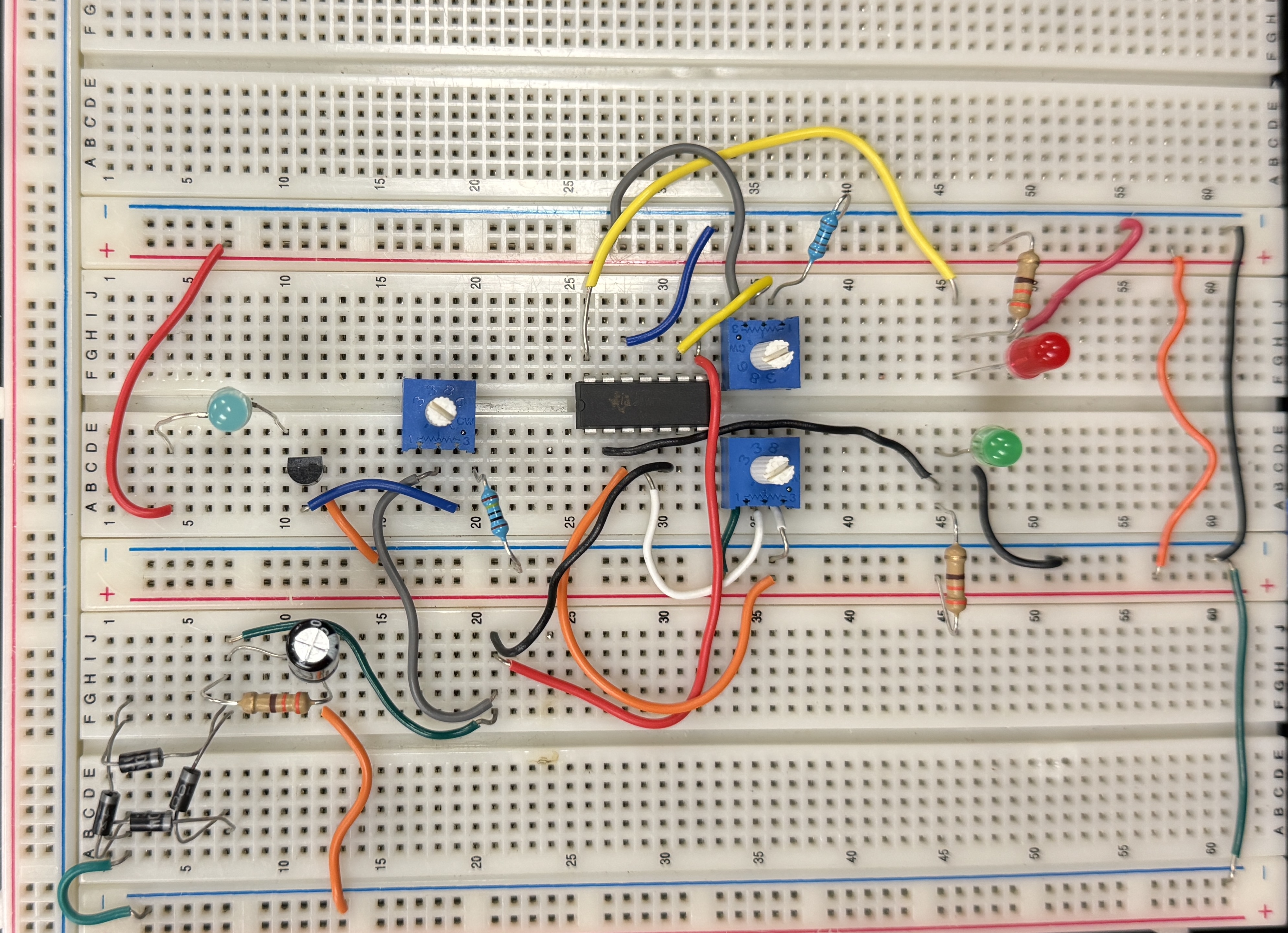
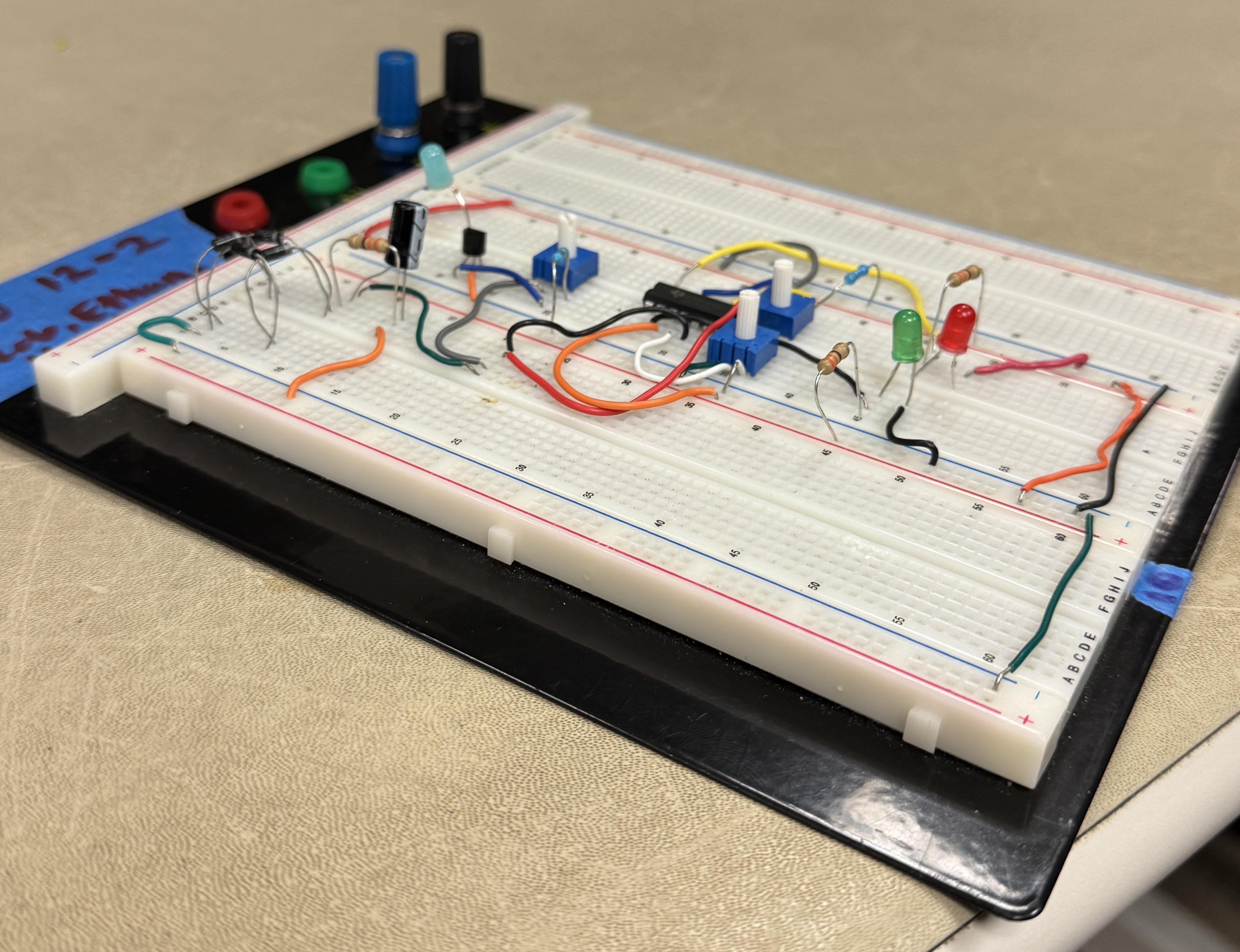
- Designed a full-wave rectifier to convert generator output into DC
- Added filtering to improve stability and reduce flicker in the indicators
- Validated DC behavior by measuring ripple and steady-state output under load
Indicator Logic
The indicator circuit converts DC voltage into clear discrete states that reflect turbine operating speed. Comparator thresholds were tuned based on measured generator behavior rather than ideal assumptions.
- Set comparator thresholds to classify low, nominal, and high speed operation
- Used LED indicators to communicate state transitions cleanly during operation
- Adjusted threshold margins to avoid chatter during noisy transitions
Testing & Validation
Performance was verified experimentally across multiple wind speeds with direct measurements on both the raw AC signal and the conditioned DC output.
- Measured generator output with oscilloscope to confirm expected waveform behavior
- Verified rectified DC output magnitude and ripple across operating conditions
- Confirmed indicator state changes at intended thresholds during live testing
Problems Solved & What I Learned
- How to translate physical system behavior into electrical design targets
- How to stabilize real generator signals so downstream logic behaves consistently
- How to debug breadboard hardware quickly using measurement tools
- How comparator thresholds need margin to avoid noisy switching
- How to structure tests so results prove performance without hand-waving
Impact
This project delivered a complete energy conversion and indication system that was built and verified in hardware. It strengthened my ability to connect mechanical behavior to electrical design decisions and reinforced the habit of validating assumptions through measurement and repeatable tests.